Geometric Design of Highway Engineering
The geometric design of roads is the branch of highway engineering concerned with the positioning of the physical elements of the roadway according to standards and constraints. The basic objectives in geometric design are to optimize efficiency and safety while minimizing cost and environmental damage.
Geometric design also affects an emerging fifth objective called “livability,” which is defined as designing roads to foster broader community goals, including providing access to employment, schools, businesses and residences, accommodate a range of travel modes such as walking, bicycling, transit, and automobiles, and minimizing fuel use, emissions and environmental damage.
Geometric roadway design can be broken into three main parts: alignment, profile, and cross-section. Combined, they provide a three-dimensional layout for a roadway.
1- Alignment is the route of the road, defined as a series of horizontal tangents and curves.
2- Profile is the vertical aspect of the road, including crest and sag curves, and the straight grade lines connecting them.
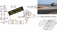
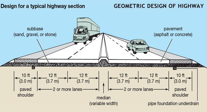
3- Cross section shows the position and number of vehicle and bicycle lanes and sidewalks, along with their cross slope or banking. Cross sections also show drainage features, pavement structure and other items outside the category of geometric design.
Pavement specialty
1- Longitudinal friction is equal to 0.35 to 0.4
2- Lateral friction is equal to 0.15
3- The highway must not be light reflecting in day, but light reflecting in night.
4- Permitted differences or unevenness must not be more than 150 cm/km.